Distortion Measurement and Correction for Coordinate Metrology with CCD-Camera
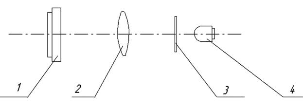
Optical diagram: 1 – CCD matrix, 2 – lens (focal length f = 20 mm), 3 – photomask with object, 4 – light-emitting diode
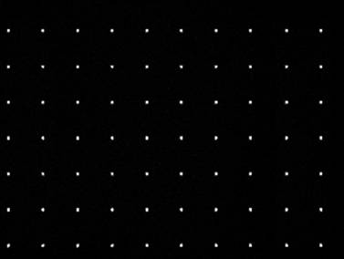
Set of dot patterns on CCD matrix to examine stability of dots positioning relative to array of readings (dot matrix 10x7)
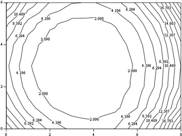
Deviation of dot coordinates from estimates due to distortion, shown as isolines (in increments of 2.1 mcm)
|