New concept of angle measurement; Simulation and experimental studies
Korolev А.N., Lukin A.Ya., Polishchuk G.S.
Among great number of known precision converters
and angle measuring instruments, optical-electronic devices with rasterization
and code conversion are the most perfect ones. Those types of measuring
instruments are produced in Russia (SKB IS [1]) as well as abroad (HEIDENHAIN
GmbH (Germany) [2] and RENISHAW (Great Britain) [3]).
In such angular optoelectronic raster converters
radial or cylindrical raster scale which is read by the analyzer made in a form
of a raster as well is used as angular measures. For the precise convertors the
amount of lines in the raster reaches few hundreds of thousands when the spacing
between the lines equals to few micrometers. Therefore the dimensions of glass
disks with raster scale are 20-30 sm. Due to the high requirements to stability
of positional relationship of analyzer and measuring raster the convertor need
to be mounted on the high precision spindle using precision or air pressure
bearings.
For accuracy level of few seconds of arc and less
the principal limitation of such devices are:
- large scale and weight;
- limitations of measurement accuracy
due to backlash and vibration influence;
- high cost.
The objective of this paper is the description of
new concept of angle measurements, based on measurement of rotation angle of a target
(represented as an ordered set of single-type elements) image, relative to the
rectangular coordinate system of rows and columns of digital camera
photodetector [4], and also the analysis of some results of simulation and
experimental study of new measurement technology.
Let us formulate the main distinct peculiarities of new angle
measurement concept.
First of all, it is the transfer from analysis of 1D raster scale to
analysis of 2D information field which requires brand-new design concepts and
data processing technology. The important factor here is the high level of
averaging of target elements coordinates that is proportional to M2,
where M is the number of elements in the measuring field, since calculation of
weight-average coordinates is performed for M elements along the X axis and for
M elements along Y axis. The total number of elements in analyzed field can
reach few hundreds.
Secondly, due to the high level of averaging, measuring system becomes
extremely tolerable to such destabilizing factors as detector noise and etc. As
a result the new measurement technology has high resolution that allow us to
use small size measuring field. Therefore, the measurement error on the level
of 1 second of arc can be obtained on the light-sensitive array with dimension
less than 10 mm. Which is almost two orders smaller than dimension of raster
sensors.
Thirdly, as a consequence of new technology there is no connection of
angle measurement results to rotation axis. It is obvious that any transversaltranslational
displacements will not change the results of angle measurement. This effect
makes the new technology essentially different from well-known technologies
described above.
Fourthly, it should be noted that new angle meter can be certified via
standard with its further mounting on the measuring object which is impossible
for raster convertors mentioned above.
In the fifth place, the possibility of target images synthesis with any
random rotation angle with high precision allow us to obtain angle standards in
the form of digital files. This is completely new case in metrology. But in a
sense there is no contradiction in this. Because, unlike majority of
measurands, angle, by definition, is dimensionless value.
All listed above characteristics and capabilities taken together allow
us to speak about new conception of angle measurement that can serve as the
basis for development of wide class of rather simple, compact and reasonably
priced sensors and plane angle meters with different purposes and accuracy
level.
It is worth mentioning that for this
technology number of measurements per unit time is determined by frame
frequency of TV camera. Therefore, in order to increase operation speed,
high-speed TV cameras with high frame frequency should be used.
Fig. 1
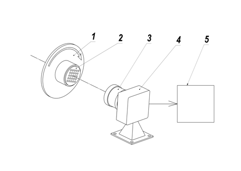
Scheme of
angle measurement device that illustrates the new conception is represented on
the fig.1. Optical target 2 with the lamp rotates along with rotor 1 and is
imaged by the lens 3 on the photodetector of digital camera 4 and then is send
to the computer 5, which performs conversion and data processing, ensuring
determination of target rotation angle relative to photodetector array.
The optical target configuration is a 2D set of
elements with known positioning, for example, orthogonal grating composed of
circle elements with relative brightness 1 on the background with relative
brightness 0.
Due to the fact that orthogonal grating has rotation symmetry for
certain angles (0, 90, 180 and 270 degrees), labels that uniquely determine
target orientation are required. Three elements of the target that have larger
diameter than other ones form scalene triangle. The position of this triangle
is used for determination of grating orientation and ensures measurement range
0-360о.
It is obvious, that by increasing the number of elements in the array
and dimensions of digital camera photodetector we can obtain the higher
measurement accuracy. At the same time, element dimensions (the circle
diameter) determines the accuracy of element coordinate determination and by
decreasing it we decrease accuracy. The optimal configuration involves a
certain compromise between elements diameter and array spacing.
It is obvious, that in current scheme target can be set even at
considerable distance from rotor rotation axis.
In this paper we do not discuss sensor design, optimal parameters of the
target and peculiar algorithms of video data processing and transformation that
are designed to obtain the angle magnitude.
Fig.2 shows angular scale of experimental angle measuring instrument
alongside with measurement result and software program panel with elements of
data input and measurement process control, that include image of optical
target. As a radiation detector we used TV camera BR-1340LM-UF [5] with 5.7 by
6.3 mm CMOS*) matrix (1280х1024 pixels, one pixel 5.2х5.2 mkm),
lens magnification equals to 1.
Fig. 2
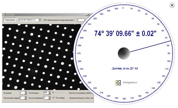
On the bottom of program panel you can see input windows: “Accumulation
of frames” – 3, “number of measurements” – 3. This means that for single
measurement we need to carry out the accumulation of three frames. In order to
receive the result presented on the dial plate we used three measurements. When
more than one measurement is used we need to calculate the MSE of measurement
result. The MSE is then shown on the dial plate near measured angle value as
“± 0.02"”. For multiple metering in the same angular position during about
one minute, repeatability of measurements amounted to 0.08".
Quite a number of factors affect measurement result. However, the affect
of such characteristics of detector as nonlinearity of light characteristic,
dark noise, photon noise, irregularity of pixels sensitivity, charge spreading
(blooming) and etc. can be minimized with the help of different algorithmic
tools.
In this case, main factors that determine measurement error are
quantization noises and anisotropic distortion of the lens, which lead to the
deterministic shifts of some elements of the target. Since sampled digital
image of the target is a picture of overlap of two periodic structures
(periodic structure of target elements and structure of light sensitive array),
resonance beat patterns appear in certain positions that lead to elements displacements
and tempering of measurement results. These deterministic shifts make essential
contribution to the measurement error and even can give isolated spikes out of
3σ,
where σ is MSE of random deterministic measurement error in the measurement range 0-360о. These
spikes can be reduced by implementation of stochastic deviation of target
geometry with regard to elements diameter and spacing between them. This
variant was successfully tested during model studies.
Peak value of lens distortion in the experimental prototype of angle
measurer on the edge amounted to just few microns. For the target with periodic
structure of elements precise measurement of lens distortion can be easily
conducted. Such magnitude of distortion lead to the measurement constant error
in each point of angular scale, and its peak value can reach 10-15 seconds of
arc. Use of optics with higher quality can significantly reduce this error
fraction, and in the case of zero distortion exclude it at all.
Metrological certification of experimental prototype of angle meter was conducted using Measuring Rotary table (MRT) which uses raster method of
angle measurement and holographic angular scale with raster spacing about 1 mkm
and diameter 180 mm. MRT was made in the Laboratory of informational-measuring
systems of B.P.Konstantinov Petersburg Nuclear Physics Institute RAS [6]. This device is used in the
Laboratory of angular measurements D.I. Mendeleev Russian National Research
Institute of Metrology as a part of National Angle Standard, its estimated
accuracy is about 0.2 seconds of arc.
At first we conducted the calibration of angle-meter in the range 0-360о in
increments of 1 degree. Received set of points describes constant error of
angle-meter, associated with distortion. This smooth enough function is carried
into the software memory and allows to implement correction in any point of the
scale. Cubic interpolation is conducted in order to calculate the correction
value inside 1 degree intervals.
Fig. 3
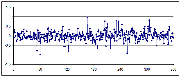
Graph 3 represents the deviation of readings of experimental prototype
of angle meter from mentioned above standard angle measuring device in the
range 0-360 degrees with correction of constant error taken into account.
Standard deviation of single measurement error is 0.25", peak deviation is
about 1".
It is rather complex to experimentally determine optimal target
configurations and limiting metrological capabilities of this new measurement
technology during the study.
Therefore it became obvious, that it is necessary to develop
mathematical model of angle measurement device with target image generator for
any possible rotation angle and standard for such meter algorithm of target
image processing and angle calculation. The development of software for target
image generation is interesting also in connection with the possibility of
developing the digital angle standards for this technology in the form of image
files.
For the correct and complete description of target image in the
simulation program, generator should take into account the following
parameters: 1) size of photodetector matrix in pixels, 2) diameter of target
elements, 3) target array spacing, 4) lens modulation transfer function, 5)
noises of photodetector matrix, 6) number of frames used for averaging of
results for single measurement, 7) number of measurements used for averaging in
order to receive final measurement result.
The influence of the distortion was not taken into account in this
model.
The main problem of developing a new model was the generation of sampled
image of the target for arbitrary angle. It is rather difficult to generate
such data array based on the analytical description of the array elements with
the help of bit-by-bit integration. Therefore we applied, used in the work [7],
method of generation of sampled target elements with fractional center of
gravityshift
relative to the array of readings.
Let the x0n,k, y0n,k be the coordinates of
circular aperture centers along gratings rows n and columns k for rotation
angle α =
0. Center coordinates after rotation by the arbitrary angle α were
calculated according to well-known formula of coordinates transformation:
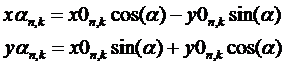 (1). (1).
After division of center coordinates by pixel size of specific CCD
(CMOP) matrix we obtain coordinates values in fractions of pixel
After division of center coordinates xαn,k and yαn,k of the element with number n,k by pixel size of CMOP matrix we
obtain coordinates values in fractions of pixel. The integer part of received
values determines the position of this element in the sampled image of the
target, while the fractional part is used to synthesize the image of this
element with the center of gravity shift by the fraction of a pixel.
Synthesis of discrete model of each target circular aperture consisted
of the following operations:
1. Calculation of object's
Fourier spectrum
 , (3) , (3)
where ω is the spatial frequency, Ф is direct Fourier transform. Object f(x,y) is a
circle of chosen diameter with relative brightness 1 on the background with
relative brightness 0.
2. Calculation of the image
spectrum, which was shifted and blurred by the lens, according to the following
formula:
 , (4) , (4)
where exponential factor is a phase shift, which ensures shift of the object by Δx and Δy that
correspond to fractional part of the coordinates xαn,k and yαn,k, H(ωx,ωy)
is the lens modulation transfer function (MTF), calculated according to
well-known formula for diffraction-limited system:
 , (5) , (5)
ωmax is cutoff spatial frequency of MTF.
3. Calculation of the digital array, which corresponds to the circular aperture image, shifted
relative to the array of readings by a given value of Δx and Δy,
 , (6) , (6)
where  is an
inverse Fourier transform. is an
inverse Fourier transform.
After quantization (f.e. 256 levels for 8 bit per pixel) and
normalization the obtained image of each element is inserted into corresponding
area of digital data array, that describes the complete picture of target
discrete image.
It is worth mentioning that inaccuracies of production (generation) of
target itself as well as limited number of quantization levels is the reason of
coordinate error in the form of arbitrary shift of each element relative to
ideal array of target elements for both generated target image and target image
received from digital camera in real-time. Hence follows the high requirement
to the accuracy of target making and to the number of quantization levels and
photodetector noises.
Discussed technology of target image generation for arbitrary rotation
angle involve calculation of M direct and inverse Fourier transforms where M is
the number of elements in the target. Simulation experiments for great number
of elements which include target synthesis and its measurement are
computationally intensive.
During this study we analyzed rather large amount of choices of combined
parameters of optical target but we can hardly say that the absolutely optimal
alternatives were found.
Developed model offers a possibility to investigate parameters of
desired signal for threshold angular displacements of target image. If the
measurement field is limited by the circle with diameter slightly less than
matrix diagonal, i.e. 8 mm, and rotation center is in the middle of the matrix,
extreme elements of the target while rotation to the 360о travel over
distance equal to the perimeter of circle 8 π = 25 mm. Since one complete angle contains 1296000 seconds of arc while
rotation to the 1 second of arc image of extreme elements moves over a distance
of 20 nm. And what happens with target image?
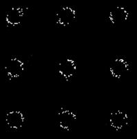
Let us take the difference between two modeling images of the target
with angular displacement equals to 1 second of arc. Computation results show
that on the edge of the elements (circular apertures) that have peak value of
displacement for about 10-12 pixels we receive difference of 1 quantizing
level, that is illustrated in the fig.4 on the magnified picture of absolute
value of images difference with normalization on full brightness. It should be
noted that on the one side of the elements (in the direction of rotation) we
obtain change of +1 quantizing level and on the other side -1 quantizing level.
The fragment presented on the fig. 4 correspond to the left upper corner of the
target image; rotation axis direction approximately through the right down
corner. In order to maintain experiment integrity image generation was
conducted without noise overlap.
Fig. 4
We conducted three different variants of virtual measuring experiment
with estimation of absolute measurement error as a difference between angle
values calculated using target images synthesized by generator and rated values
of target rotation angle for generation of its image; basic experiment
parameters are presented in the table 1.
Table 1
| Experiment
version |
Matrix
size, pixels |
Pixel
size, mkm |
Number
of target elements |
Lens
resolution, mm-1 |
Photodetector
noise, quantizing levels |
Number
of measurements |
| 1 |
1280х1024 |
5.2 |
357 |
50 |
1 |
3 |
| 2 |
3000х2200 |
3.5 |
825 |
70 |
1 |
3 |
| 3 |
5000х2200 |
4.2 |
1971 |
70 |
1 |
3 |
The results of conducted virtual measuring experiments are presented in
the table 2.
Table 2
| Experiment
version |
MSE of measurement result error (σ)
seconds of arc |
Maximum error value (3 σ)
seconds of arc |
| 1 |
0.18 |
0.53 |
| 2 |
0.04 |
0.12 |
| 3 |
0.007 |
0.022 |
Modeling results for the variant 1 are well correlated with the results
of metrological certification of experimental angle meter. Modeling results for
the variants 2 and 3, for which the matrix with significantly larger dimension
were used, show that potential metrological possibilities of new concept of
angle measurement allow us to speak about accuracy level of hundredths of
second of arc.
Conclusions:
The results of experimental and simulation studies of estimation of
metrological characteristic of the angle meter designed according to the new
conception of angle measurement were described. The concept was developed by
the authors of the paper and is based on the determination of angular position
of image of optical target on the image sensor of TV camera using special data
processing algorithms. The mathematical model of angle meter that uses target
images generator with any rotation angle in rectangular coordinates and
standard for this angle-meter data processing algorithm was developed. Metrological
study of experimental prototype showed that error of angle-meter does not
exceed 1 second of arc. Simulation study showed that potential accuracy level
of new technology of angle measurement is hundredths of second of arc.
* CMOS Complementary-symmetry/metal-oxide-semiconductor.
References
1. Booklet of SKB IS company www.skbis.ru),
2. Booklet of HEIDENHAIN GmbH company (www.heidenhain.de)
3. Booklet of RENISHAW company (www.renishaw.com)
4. Korolev A.N., Lukin A.Ya., Polishchuk G.S., the Patent RU № 109847 «Angle-Meter».
5. Booklet of ES-Experts» company (www.es-experts.ru)
6. S.V.Gordeev, B.G.Turukhano, Investigation of the interference field
of two spherical waves for holographic recoding of precision radial diffraction
gratings, Optics & Laser Technology, vol. 28, № 4, p. 255-261.
7. Korolev A.N., Gartsuev A.I., Polishchuk G.S., Tregub V.P. Metrological studies and the
choice of the shape of an optical mark in digital measuring systems. Journal of
Optical Technology. Vol. 77 Issue 6. pp.370-372 (2010).
|