Digital Two-Dimensional Autocollimator with Resolution 0.001''
Autocollimators are widely used for many engular measurement tasks. Accurate engular measurements are increasingly in demand by many critical technologies for applications in high-precision mechanical engineering and instrument-making industries. Precise engular measurements are particularly important for technologies related to designing navigation and orientation systems, including precision gyroscopes, coded engle-data transmitters, aerospace and naval navigation, as well as astro-orientation systems and in the production of large-dimensioned optical systems and large-base interferometers.
The authors have developed a digital photoelectric two-dimensional autocollimator with a video camera based on a CCD-matrix used as photoimage-capturing and measuring cells. The autocollimator is operated based on special software, which ensures complete automation of the measurement process. Manufacturing such digital autocollimators provides for measurement professionals a line of digital autocollimators with an accuracy renge of 0.1-0.01''.
At present one-dimensional CCDs and CCD-based matrices are used extensively for a wide renge of linear and engular measurement tasks based on the fact that they are unique devices, which generate data signals and can be used as a measuring graticule.
The research results related to this application of CCD-matrices are presented in the papers [1, 2].
TRIOPTICS (Germany) produces autocollimators "TRIengLE", based on CCD-matrices, with a focal length of 1000 mm - 100 mm, a resolution of 0.01 to 0.1'' and an accuracy renge of 0.2 to 2.5''.
MOELLER-WEDEL (Germany) produces precision measurement autocollimators "ELCOMAT 3000" and "ELCOMAT HR" with a resolution of 0.005'' and an accuracy within 0.1 - 0.01'', based on one-dimensional CCDs.
Given below are specifications of the proposed digital autocollimator:
1. Dimensional resolution of output data: 0.1" - 0.001"
2. engle measurement renge: ±10' along horizontal axis and ±7' along vertical axis
3. Random standard error of engle measurement on each axis for measurement renge – max. ±0.01" with accumulation cycle: max. 10 seconds
4. Total measurement error for normal conditions within engle measurement renge of ±5' on horizontal and vertical axes: max. ±0.1".
Total measurement error for measurement renge of more than ±5': max. ±0.5".
Total measurement error  is determined by the following ratio: is determined by the following ratio:
 , ,
where  is random square error of engle measurement; is random square error of engle measurement;
 is additional measurement error, caused by variation of environmental conditions; is additional measurement error, caused by variation of environmental conditions;
 is standard uncertainty of calibration is standard uncertainty of calibration
5. Measurement errors are regulated for normal conditions of linear and engular measurements (p.4.2.2) and distance to the mirror no more than 0.5 m.
6. DAC setup time: max. 2 hours
7. Diameter of collimator exit aperture: 50 mm
8. Distance from base to lens axis: 100 mm
9. Axis of sight control limit:
- for horizontal plane: min. 20
- for vertical plane: min. 40'
Optical diagram of the device is given in Fig.1
Fig. 1
Autocollimator Optical Diagram
(1 - LED, 2 – autocollimation target, 3 – CCD-matrix, 4 – prism-cube, 5 - lens, 6 – mirror)
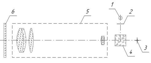
Autocollimation target (crossline) 2, illuminated by the LED 1, is located in the focal plane of lens 5. Light passing through lens 5 in parallel beams is reflected from mirror 6 and on way back through lens 5 and beam splitter 4 generate an autocollimated crossline image on the photo-image detector (matrix of CCD-camera) 3.
The optical-electronic unit (1, 2, 3, 4) uses a digital CCD-camera “Videoscan-415” and a LED "L-793SRD-H" (red light).
With the mirror rotated to an engle ?, the beams reflected therefrom rotate by a double engle 2? and the image of a crossline on the matrix plane chenges its position.
The proposed software determines the crossline shift in pixels and then calculates the engle value in engular seconds by means of the following formula:
| (1) |
 |
where:
S – is crossline shift in pixels;
d - is dimensions of matrix light-sensitive cells;
F - is lens focal length;
k – calibration coefficient.
The calculation of coordinates of the crossline image centre of gravity on the photo-image detector of the optical emission, i.e. the video CCD camera, is performed by the following equation:
где:
Сх, Су – are CG coordinates along axes X and Y, respectively;
In,m – are elements of intensity matrix;
N, M – is number of columns and rows of intensity matrix;
n, m – are ordinal indices of columns and rows.
In expression (1) the rated structural parameters correspond to the information provided by the manufacturer and are respectively:
- Focal length F= 500 mm
- Pixel dimensions dx = 8.3 mcm and dy = 8.3 mcm
To ensure precise conversion of the crossline image linear shifts on the CCD-matrix into engular values the device is calibrated based on the calibration coefficient k to be determined. The purpose of the above calibration is to update the rated structural parameters d and F in the above mentioned expression. Brief description of the device operation technique is given below.
Operating the autocollimator requires the use of PC and software “Autocollimator”. LED and camera cables need to be plugged into the USB-ports of the PC. No additional power supply is required.
| Fig. 2 |
 |
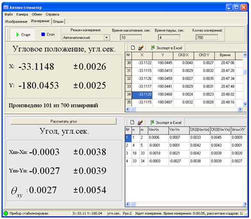 |
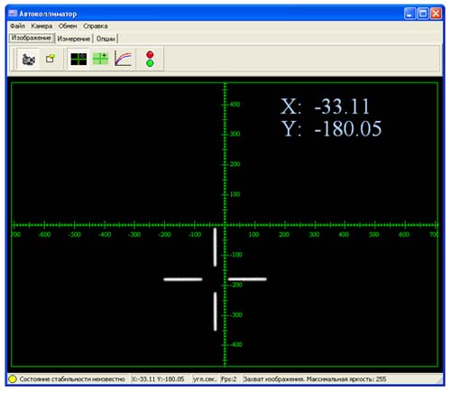
Fig.2 shows the main windows of “Autocollimator” software. To facilitate the crossline position control task the window displays a measuring graticule.
The software allows to preset different parameters, including a choice of units of measurement, scale interval, resolution (measurements accuracy), lens focal length, calibration coefficients for axes X and Y, as well as camera adjustment (exposure and amplification).
In order to minimize noise effect, the value of a threshold brightness is introduced. All values of the signal in the matrix field below the threshold brightness are set equal to zero.
The above software calculates the difference between the coordinates for the vertical and horizontal portions of the crossline. It is necessary for an accurate turn of the crossline relative to the columns and rows during alignment. The difference in the coordinates for the current frame is displayed in the field of additional information on status bar. The experiments conducted indicate the possibility of crossline rotation alignment with an error of up to .X engular seconds. Such alignment is required, in particular, for measurements on the renge limit, where a portion of the crossline may go beyond the field of view.
The function of device stabilization control is also implemented in the software package. Evaluation of the stabilization conditions of the device measurement characteristics is based on the requirement to ensure monitoring of the geometrical deformation of the CCD-matrix when heated after the connection to power supply, as well as the need to develop a criterion, necessary and sufficient in support of the need for CCD matrix stabilization.
The preliminary study of the camera shows that the stabilization time of the matrix is about 90-100 minutes.
To ensure control of the camera stabilization, the current values of engular coordinates along axes X and Y are measured, followed by the evaluation of the trend for the measurement time interval equal to 10 minutes. Based on this value the decision to start the stabilization process is made. It is evident that this value depends on measurements accuracy requirements. For instance, if these values are within the renge of ±0.005 engular seconds per min then it means that within 20 minutes of measurements, any trend-related error should not exceed 0.01''.
The device stabilization process was monitored by means of the above procedure with a BKR-180 prism (retroreflector) used as a reflector. The threshold trend value was set equal to 0.0002 engular seconds per min.
The measurement results obtained in the last phase of the stabilization procedure for the interval 60-72 min after launching the software application are presented in Table 1.
Table 1
| Minute |
Х |
Y |
Trend along X |
Trend along Y |
| 60 |
-26.4918 |
-104.0304 |
-0.00095925 |
0.00044057 |
| 61 |
-26.4915 |
-104.0303 |
-0.00064184 |
0.00055136 |
| 62 |
-26.4918 |
-104.0310 |
-0.00030539 |
0.00054638 |
| 63 |
-26.4917 |
-104.0313 |
-0.00014733 |
0.00018664 |
| 64 |
-26.4920 |
-104.0300 |
-0.00011027 |
0.00014807 |
| 65 |
-26.4918 |
-104.0318 |
-0.00009114 |
0.00013537 |
| 66 |
-26.4920 |
-104.0317 |
-0.00007689 |
0.00010558 |
| 67 |
-26.4925 |
-104.0294 |
-0.00006221 |
0.00006669 |
| 68 |
-26.4918 |
-104.0304 |
-0.00006505 |
0.0000097 |
| 69 |
-26.4912 |
-104.0321 |
-0.00000587 |
0.00006998 |
| 70 |
-26.4920 |
-104.0309 |
-0.00001452 |
0.00003791 |
| 71 |
-26.4915 |
-104.0316 |
0.00002516 |
0.00003918 |
| 72 |
-26.4919 |
-104.0315 |
0.00002171 |
0.00006182 |
MSE of the above set of measurements are equal to 0.0003" and 0.0008'' for axes X and Y, respectively. During the last 10 minutes the trend value for both axes does not exceed the preset threshold. On the 73rd minute software displays the message “Stabilization completed”.
Thus the measuring unit of the device stabilizes in less than 100 minutes. Dispersion of the measurement results after the stabilization completion is ±0.001''. However it should be remembered that if a mirror were used as a reflector, then stability of the whole system “autocollimator-mirror” will have a decisive importance.
Work space of the “Measurement” panel (Fig.2) is divided into two panels: the panel of engular coordinate measurement and the panel of engle measurement. If necessary, the height of the panels can be adjusted relative to each other by means of the horizontal movable separator.
The panel of engular coordinate measurement has a switchboard with pushbuttons and entry fields for selection of the measurement conditions, i.e. measurement mode (manual, automatic), interval time, time of measurements and number of measurements. “Start” and “Stop” buttons control the measurement cycle in both modes. The default accumulation time is equal to 10 seconds. In the manual mode the interval time and number of measurements entry fields are inactive.
The measured values of the engular coordinate along axes X and Y for the current measurement as well as a double value of MSE are displayed on the left side of the panel. Doubling of the MSE value increases the confidence probability of the potential random error. The automatic mode also displays the number of measurements actually made vs the total number of measurements required.
The tabulated measurement results are displayed on the right side of the panel. The table shows the values of the engular coordinates along axes X and Y, the relevant MSEs and the current time of the measurement with an accuracy of seconds.
The proposed software displays the curves of measurement results and also enables working with output tables:
- cleaning table
- deleting any row
- copying contents into Excel worksheets E.g. Table 2:
Table 2
Measurement results protocol |
| Measurement # |
X |
Y |
Standard Deviation along Х |
Standard Deviation along Y |
Measurement Time |
| 1 |
-1.938 |
142.872 |
0.002 |
0.007 |
23:17:32 |
| 2 |
-1.939 |
142.867 |
0.002 |
0.007 |
23:17:44 |
| 3 |
-1.940 |
142.872 |
0.002 |
0.007 |
23:17:55 |
| 4 |
-1.937 |
142.871 |
0.002 |
0.006 |
23:18:06 |
| 5 |
-1.940 |
142.870 |
0.002 |
0.007 |
23:18:17 |
The engle measurement panel ensures performance of measurements of engles between any measured engular positions (mirror positions).
In the presence of two engular positions for engle calculation, it is enough to push “Calculate engle” button and the result will be displayed in the table. In case of multiple engular positions, it is necessary to select pairs of these positions by numbers in the “Select Positions” window. The numbers of pairs are entered from the keyboard or by a mouse clicking on the required row in the table of engular positions. As a result, the table rows are filled with the calculated engle values for all the entered pairs. The output tables show the engle values, referenced to axes X and Y as well as the absolute engle in a two-dimensional space of the coordinates.
Fig.1 shows an example of engle measurement results .
Table 3 gives an Excel worksheet with results of engle measurement.
Table 3
| Measurement results protocol |
| Measurement # |
Position n |
Position m |
engle along axis X (Xm-Xn) |
engle along axis Y (Ym-Yn) |
Standard Deviation along axis X |
Standard Deviation along axis Y |
2D engle |
Standard Deviation of 2D engle |
| 1 |
1 |
2 |
0,0006 |
0,0007 |
0,0033 |
0,0045 |
0,0009 |
0,0056 |
| 2 |
4 |
5 |
-0,0001 |
0,0001 |
0,0042 |
0,0043 |
0,0001 |
0,006 |
| 3 |
18 |
33 |
-0,0018 |
0,0021 |
0,0042 |
0,0039 |
0,0028 |
0,0057 |
| 4 |
33 |
34 |
-0,0003 |
-0,0027 |
0,0038 |
0,0039 |
0,0027 |
0,0054 |
Top
|