Precision of Image Positioning on CCD-Camera
The purpose of this work was experimentation with the coordinate stability of light-sensitive cells of CCD matrices, as well as accuracy evaluation of in image positioning tasks.
A matrix of light-sensitive cells of modern digital photo cameras and CCD-cameras is a product of microelectronics technologies and represents a 2D array of elements, whose dimensions have an accuracy of no more than hundredths of micrometer. The number of light-sensitive cells can amount to several millions with the dimension of each element and the array pitch – a few mcm. Taking into account the orthogonal topology and the distinct nature of these structures, it is reasonable to use them for addressing precision metrological tasks. However, there are a lot of factors which affect the accuracy of measurements involving CCD matrices, including the structure dimensional resolution, complex charge transfer processes, matrix noise, mechanical and vibration effects, thermal drift of matrix cells occurring due to a significant heat release during operation. Research of extreme accuracy of image positioning on the CCD matrix is also a subject of interest. It is obvious that in this case we are dealing with a limited image category of simple objects like dots, lines and crosslines that are used for precise optical measurements.
The above research was conducted on the digital CCD-camera with a Peltier cooler and a 12-bit ADC. This camera has a high linearity for low levels of illumination and a principal unit “lens thread ring gage – matrix - cooler” executed as a monobloc, which ensures high mechanical stability of the matrix position relative to the optical system. Dimension of the light-sensitive cell (or array pitch) is 8.3х8.6 mcm.
In order to minimize mechanical and thermal effects, research was conducted with a short-focus optical system (f = 20 mm), with a magnification of 0.8х.
To conduct research we designed a special program of video data processing, image CG calculation and measurements statistical processing for multiframe accumulation.
Metrological research of the matrix was conducted in two phases. The first phase comprised research of the temporal trend of coordinates of the matrix discrete cells by measuring dot image coordinates that cover the entire matrix field. The second phase was devoted to the examination of the accuracy limits in positioning of a test object featured by a crossline. For matrix stabilization the cooler temperature renge of +10 -15oС was chosen, which is lower than the standard temperature for precise linear measurements (+ 20oС), but does not yet lead to strong temperature variations between the matrix unit and the environment.
While a set of dot-matrix images was projected on the CCD-matrix, the special program performed CG calculations for each dot in each frame. The measurement results were averaged within the limits of the accumulation interval.
The results given below correspond to an accumulation interval of 50 seconds. For a video data input speed of 4 frames per second averaging of 200 frames is done in each accumulation interval.
Fig. 1.

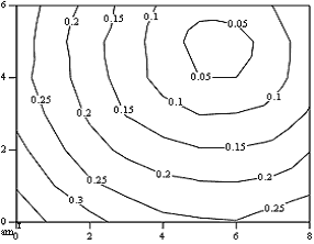
Fig.1 shows a field of isolines of the shift of coordinates of light-sensitive cells of the matrix for an interval of 200 minutes after the camera with a pitch of 0.05 pix is turned on. (It is worth mentioning that the above shift values are, in fact, related not to isolated pixels, but to a certain region, a set of pixels, involved in the dot object image rendering. Further for the sake of simplicity we will discuss the shift of pixel, which is central for this region.) The ambient temperature was +18oС, the cooler temperature was +10oС.
The absolute values of shifts expressed in fractions of a pixel, are given in Table 1. The minimum and maximum values are shown in bold print. The vectors shifts in each dot in the field are oriented toward the stabilization center with a shift value close to zero, which is indicative of matrix compression relative to the center.
Table 1.
| Dot |
0 |
1 |
2 |
3 |
4 |
5 |
6 |
7 |
8 |
| 0 |
0.397 |
0.339 |
0.317 |
0.283 |
0.263 |
0.256 |
0.253 |
0.270 |
0.295 |
| 1 |
0.345 |
0.302 |
0.259 |
0.236 |
0.215 |
0.207 |
0.206 |
0.214 |
0.235 |
| 2 |
0.316 |
0.265 |
0.219 |
0.189 |
0.168 |
0.153 |
0.153 |
0.163 |
0.198 |
| 3 |
0.286 |
0.239 |
0.192 |
0.147 |
0.118 |
0.099 |
0.101 |
0.116 |
0.155 |
| 4 |
0.269 |
0.222 |
0.176 |
0.126 |
0.081 |
0.050 |
0.050 |
0.081 |
0.129 |
| 5 |
0.277 |
0.220 |
0.166 |
0.125 |
0.075 |
0.030 |
0.028 |
0.075 |
0.128 |
| 6 |
0.285 |
0.231 |
0.185 |
0.133 |
0.092 |
0.065 |
0.074 |
0.100 |
0.146 |
The isolines field in the form of a system of concentric circles demonstrates a highly isotropic nature of the matrix deformation process. On the basis of the shift values (see Table 1 and Fig.1) we can determine that the thermal deformation leads to a variation in the pitch of readings of the matrix array by approximately 6 nm. This deformation accounts for less than 0.1% of the initial pitch. However it is obvious that for accurate measurements it is necessary to calibrate the measuring device after the stabilization to rule out any thermal deformation effect.
As can be seen from Table 1, the maximum shift value is 0.4px. This means that the matrix light-sensitive cells shift by a value of up to 3.5 mcm. Stabilization occurs approximately three hours later and the shifting of the light-sensitive cells stops.
Fig. 2.

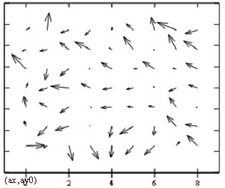
The vector field of the shifts of the position of the matrix light-sensitive cells within a time interval of 10 minutes between the two cycles (i.e. between the 200th and the 190th minutes) following the three hours stabilization process is represented in Fig.2. The relevant absolute values of the shift in fractions of a pixel are given in Table 2. Values which equal to and exceeding 0.001px are shown in bold print.
Table 2
| Dot |
0 |
1 |
2 |
3 |
4 |
5 |
6 |
7 |
8 |
| 0 |
0.001 |
0.0011 |
0.0002 |
0.0006 |
0.0002 |
0.0006 |
0.0009 |
0.0005 |
0.0006 |
| 1 |
0.0001 |
0.0005 |
0.0008 |
0.0005 |
0.0001 |
0.0011 |
0.0001 |
0.001 |
0.0008 |
| 2 |
0.0009 |
0.0008 |
0.0006 |
0.0001 |
0.0007 |
0.0003 |
0.0005 |
0.0004 |
0.0003 |
| 3 |
0.0003 |
0.0005 |
0.001 |
0.0006 |
0.0005 |
0.0004 |
0.0001 |
0.0005 |
0.0005 |
| 4 |
0.001 |
0.0003 |
0.0006 |
0.0001 |
0.0006 |
0.0002 |
0.0006 |
0.0006 |
0.0006 |
| 5 |
0.0004 |
0.0007 |
0.0005 |
0.0008 |
0.0007 |
0.0007 |
0.0005 |
0.0008 |
0.0008 |
| 6 |
0.0002 |
0.0002 |
0.001 |
0.0008 |
0.0007 |
0.0007 |
0.0006 |
0.0011 |
0.0009 |
As follows from Fig.2 and Table 2, the average value of the shifts is equal to 0.0006px. This value is consistent with the estimated error of the dot objet image CG determination, which is expressed as a relatively low number of pixels (about 50) involved in the signal generation process.
In general the shift vector field is completely randomized, however the high measurement accuracy illustrates that the maximum shift values (0.001px and higher) have certain peripheral points. These variations may be due to edge thermostabilization effects. Possible topological causes of these overshoots for the peripheral points require further investigation.
Thus, the above study shows that principal array of the matrix light-sensitive cells after stabilization acquire a high coordinate stability (around 0.001px), and that the matrix can be used for precise measurements.
The accuracy limits for image positioning was analyzed using a test object (crossline) by examining the image CG position variation in time for a maximum stable condition of the matrix three hours after it was turned on. The benefit of the crossline compared with a dot object is that in signal generation for this kind of object a hundredfold number of matrix light-sensitive cells is required. The integral procedure of the CG calculation leads to a significantly more efficient noise averaging results. Indeed, if fluctuations for dot object CG coordinates are 0.02-0.03pix, for the crossline they do not exceed 0.003pix.
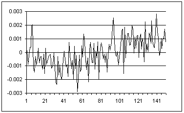
In measuring the crossline CG coordinates for a measurement cycle of 200 measurements in 50 seconds, the variation spread does not exceed 10 nm (the standard deviation is 3 nm).
The measurement results are equal to the average value for a cycle of 200 measurements; the measurement error is double the value (confidence probability is 95%) of a standard deviation of the mean value. It is clear that the standard uncertainty of the measurement is 0.3 nm.
Fig. 3.

Fig.3 shows a curve of deviation from the mean value along axis X for successive CG coordinate measurement cycles of 150 minutes. MSE for this sequence of measurements is 1 nm.
Top
|

